Phasors
Motivation
Sometimes dealing with sinusoidal signals in the time domain can be a hassle. Consider finding the steady-state current of the circuit below, with \(v(t)=V_0\cos(\omega{}t+\phi)\).
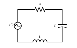
From circuit theory, we know that the capacitor current is proportional to the derivative of the voltage, while the current across the inductor is the integral of the voltage. Therefore, using Kirchoff’s voltage law,
\[v(t)=\frac{1}{C}\int_{-\infty}^{t}i(x)dx+L\frac{\text{d}i(t)}{\text{d}t}+Ri(t)\]I don’t know about you, but that’s not an integro-differential equation I can solve very easily. Luckily, thanks to Charles Proteus Steinmetz, there’s a better way.
Derivation
If one were trying to find a simpler way to solve our problem, one might begin with the fact that this cicrcuit’s input frequency equals its output frequency. We might therefore seek a time-independent quantity that carries the the magnitude and phase of the signal to simplify the analysis. A phasor is just such a quantity, and we’ll use Euler’s indentity to find it. We begin by recognizing that our cosine function is in fact the real part of a complex exponential.
\[\begin{align*} v(t)&=\mathcal{Re}\{V_0e^{j(\omega{}t+\phi)}\}\\ &=\mathcal{Re}\{V_0e^{j\omega{}t}e^{j\phi}\}\\ \end{align*}\]Ignoring the time-dependent exponential, the phasor becomes \(V_0e^{j\phi}\). The phasor transform is carried out by representing a sinusoidal signal with its phasor, or
\[\tilde{V}=V_0e^{j\phi}=\mathcal{P}\{V_0\cos(\omega{}t+\phi)\}\]But why is it useful? To find out, let’s take each element in our circuit and find its \(VI\) relationship in phasor form. Beginning with the resistor, we start with Ohm’s Law and perfrom the phase transform to both sides to obtain
\[\begin{align*} v(t)&=RI_0\cos(\omega{}t+\phi)\\ &=\mathcal{Re}\{RI_0\cos(\omega{}t+\phi)\}\\ \tilde{V}&=R\tilde{I} \end{align*}\]Next, let’s perform similar steps with the inductor.
\[\begin{align*} v(t)&=L\frac{\text{d}}{\text{d}t}I_0\cos(\omega{}t+\phi)\\ &=-\omega{}LI_0\sin(\omega{}t+\phi)\\ &=-\omega{}LI_0\cos(\omega{}t+\phi-\pi/2)\\ &=-\omega{}L\mathcal{Re}\{I_0\cos(\omega{}t+\phi-\pi/2)\}\\ &=-\omega{}L\tilde{I}e^{-j\pi/2}\\ \tilde{V}&=j\omega{}L\tilde{I} \end{align*}\]where we have used the identity \(e^{-j\pi/2}=-j\). Finally, we address the capacitor.
\[\begin{align*} v(t)&=\frac{1}{C}\int_{-\infty}^{t}I_0\cos(\omega{}t+\phi)dx\\ &=\frac{1}{\omega{}C}I_0\sin(\omega{}t+\phi)\\ &=\frac{1}{\omega{}C}I_0\cos(\omega{}t+\phi-pi/2)\\ &=\frac{1}{\omega{}C}\tilde{I}e^{-j\pi/2}\\ &=\frac{-j}{\omega{}C}\tilde{I}\\ \tilde{V}&=\frac{1}{j\omega{}C}\tilde{I} \end{align*}\]In the phasor representation, also known as the frequency domain, we define the concept of impedance to current flow, \(Z=\tilde{V}/\tilde{I}\), for each of the above elements as
\[Z_R=R\qquad{}Z_L=j\omega{}L\qquad{}Z_C=\frac{1}{j\omega{}C}\]Method
Let’s revisit our original problem, this time replacing all the time-dependent quantities with phasors.
\[\begin{align*} \tilde{V}&=\frac{1}{j\omega{}C}\tilde{I}+j\omega{}L\tilde{I}+R\tilde{I}\\ &=\tilde{I}(\frac{1}{j\omega{}C}+j\omega{}L+R)\\ \end{align*}\]Solving for current,
\[\begin{align*} \tilde{I}&=\frac{\tilde{V}}{R+j(\omega{}L-\frac{1}{\omega{}C})}\\ &=\frac{\tilde{V}e^{-j\theta}}{\sqrt{R^2+(\omega{}L-\frac{1}{\omega{}C})^2}}\tag{$\theta=\tan^{-1}(\frac{\omega{}L-\frac{1}{\omega{}C}}{R})$}\\ \end{align*}\]Now we can convert these quantities back into the time domain for the final solution.
\[\begin{align*} i(t)&=\mathcal{Re}\{\frac{\tilde{V}e^{-j\theta}}{\sqrt{R^2+(\omega{}L-\frac{1}{\omega{}C})^2}}e^{j\omega{}t}\}\\ &=\frac{V_0}{\sqrt{R^2+(\omega{}L-\frac{1}{\omega{}C})^2}}\cos(\omega{}t-\theta)\\ \end{align*}\]